Deliverable #5: Conclusion

General Conclusion:

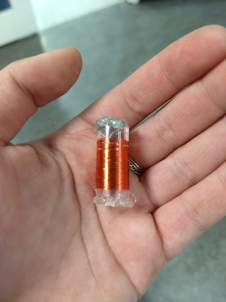
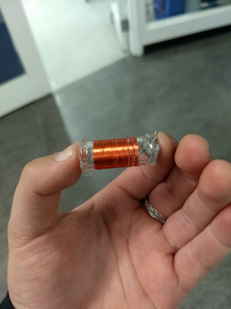
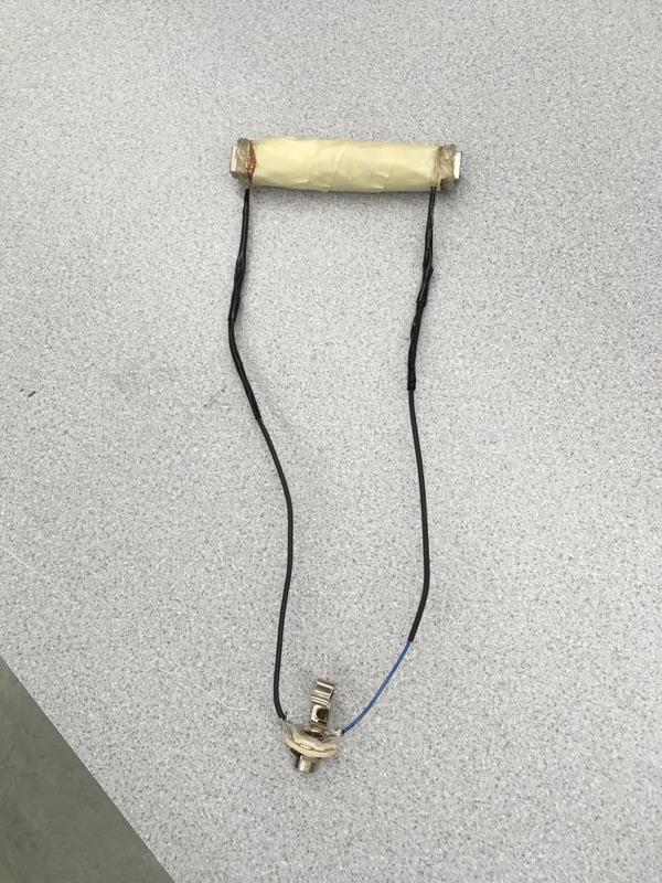
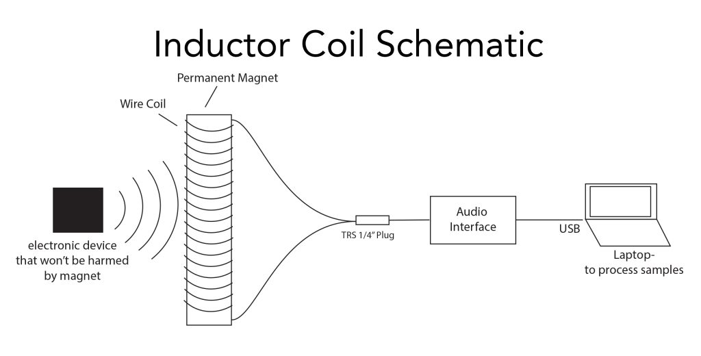
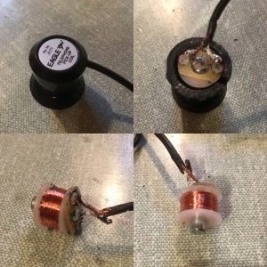
Over the course of this project, we have explored primarily three engineering principles: building/shop-work, induction, and audio engineering. We ultimately created a functioning, if not noisy, inductor coil pickup, which we used to collect various electrical signals which are not typically interpreted as audio. We had no way of predicting what our samples would sound like, as there appears to have been minimal prior investigation into how these signals could manifest as audio, but we were pleasantly surprised and perplexed by the variety of sounds we “found” in everyday items.


Quality of Pickup:

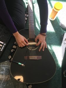
The only sample of ours for which there was a pre-existing precedent was the one of the guitar. Below are four audio samples for comparison:

1) Electric Guitar’s (Mexican Fender Stratocaster) professional-grade inductor coil pickups:

2) Acoustic Guitar’s (Seagull Acoustic-Electric) professional-grade piezoelectric pickup:

3) Our pickup used with the Seagull Acoustic-Electric (steel string guitar), unedited (noisy):

4) Same as example immediately (3) above but noise reduced with EQ adjustments:


Production Takeaways:

With the sounds recorded, we took to our DAWs. Emily used Protools, and Sean used Ableton to organize and process the samples. Emily mixed the sounds into a continuous, flowing piece that introduces each sample, one after the other. The purpose of this piece is to show both how these frequencies, which are alien to our ears, actually sound, while simultaneously laying a foundation which allows for comparison with the altered samples in the second project. Sean took these samples, and played around with them. Numerous effects (such as filters, chorus, delay, redux, etc.), VSTs, and several other audio units were used in the manipulation of these samples. The end result is a short piece which combines elements of various audio effects we’ve learned about throughout the course to create something entirely new.


What We Each Did:

We worked together very closely on the entirety of this project; we did all planning, building, and testing together. Closer to the end of the project, however, we split up the production work a little bit; Sean took the lead on the Ableton Live production of our final composition while Emily mixed the montage of raw samples in ProTools and constructed the Powerpoint presentation.


Minimally Edited, Mostly Raw Sample Montage:

In order of appearance: Digital Alarm Clock, Vending Machine Credit Card Reader, Light Switch on/off, WiFi Router, Samsung TV Remote, Xfinity TV Remote, Microwave


Final Composition:

Deliverable #4: Test

Testing and Sampling:

Initial testing of the inductor pickup has been far more successful than we had initially imagined. We met in Thayer basement to record samples of the waves emitted by various electrical devices. To record, we used a Focusrite Scarlett 2i2 (audio interface), and Audacity as a DAW to process the samples. We recorded samples from various television remotes, a digital alarm clock, a light switch, a microwave, a vending machine credit card reader, a router, and a guitar amp. The result produced a multitude of different frequency waves and patterns, which are attached below:

While recording the samples mentioned above, we found that the pickup could also be used to record voice; essentially, we stuck the pickup to the metal top of the microwave, and then by shouting at the metal (and vibrating it with the sound of our voice), the metal surface would communicate those sounds in a form the pickup could detect and record. In addition to this, we also used the pickup to record an acoustic guitar (which has ferrous strings) as well as a flute (also made of ferrous material).

The audio quality of these recordings is not perfect, as there is a lot of noise, but the fact that we were able to record audio signals from these sources at all exceeds our expectations and project goals. The recordings are attached below:

Acoustic Guitar:

Flute:

Digital Clock:

Router:

Light Switch:

Samsung Remote:

Xfinity Remote:

Microwave:

Card Reader:

Amplifier:

Deliverable #3: Build

Prototyping:

Prior to our magnet arriving, we decided to prototype the pickup using a small piece of plastic pipe and some of the 42 AWG wire. The goals with this exercise were to practice the actual winding of the wire (using the drill) as well as to become familiar with the properties of the wire, which is extremely thin and easily breakable.

After cutting a couple inches of pipe, we need a way to mount it on the drill, so we covered the tip of a drill bit in masking tape, and then hot-glued the pipe to the tape. This allowed the pipe to turn with the drill without harming the drill or bit in any way. We then put the spool of wire on a screwdriver, held horizontally, so that it would be able to freely feed wire to the turning pipe. We found that it would be important to securely anchor the starting free end of the wire using hot glue prior to starting to wind, as the wire is so fine it would be very easy to lose it or have it slip around. We also learned that the location of the wire on the pipe as we are winding is difficult to control precisely, so it would be best to stay away from the end of the magnet when coiling.

Please see below: two images of the prototype.


The Build (Attempt #1):

COILING-

Once the items that we ordered arrived, we set to work on constructing the apparatus. First, we placed the neodymium magnet on the tip of a handheld power drill, which happened to be a ferrous material. This allowed us to easily coil up the wire around the magnet by using the throttle of the drill to (at a safe speed, of course) rotate the magnet, and simultaneously wind the 42 AWG wire, which was being fed from a spool. After turning the wire for 30 minutes, we removed the magnet from the drill, and hot glued the ends of the coil to the magnet, leaving extra cable dangling off from the ends so that we could later solder them to thicker cables.

Please see below: an image of the magnet and coil.

SOLDERING-

Once the induction pickup was completed, we moved on to soldering the pickup. We used two pieces of rubber coated copper wire, stripped the ends using a wire cutter/stripper, wound the loose ends of cable around the mounts on the pickup, and soldered a connection. Once this was completed, we slid protective rubber shields over the cable, which were going to be shrunk later using a heat gun on as a measure to prevent the thin copper wire from breaking. We then began to solder the 42 AWG wire to the loose ends of the stripped cables.

At first, this was working great. However, shortly thereafter we found that it was incredibly easy to accidentally break the 42 AWG wire. We attempted to mend the situation several times by breaking the soldered connection, re-cutting and stripping the insulated wire, and then re-soldering the two cables together, but each time the mend ended up failing either due to 42 AWG wire breakage or other mechanical errors (such as the soldering iron shrinking the rubber shielding, and making it impossible to slide it over onto the thinner wire without repeating the above method, again). Eventually, we realized that there was several breaks in the coiled 42 AWG wire, so we had no choice but to cut the wire off of the magnet, and start again from square one – this time, with thicker wire.

The Build (Attempt #2):

For our second attempt, we approached the project with the same methods as before except with 26-gauge copper wire, instead of 42. This wire proved much more durable, and we were very successful working with it. We found that in one minute, we were able to wrap the wire around the magnet approximately 50 times, so we estimate that the total number of turns in our coil is approximately 700. Pictured below.

We then wrapped the entire coil in masking tape to secure and protect, and we also secured the ends of the coil in place with hot glue. Pictured below.

We then soldered the ends of the wire to pieces of insulated wire which were, in turn, soldered to a ¼” TRS jack. Pictured below.

The Next Step:

Our next step will be to begin experimenting with the pickup, investigating what kinds of sounds we’ll be able to capture and which methods will be most effective. We will use a ¼” TRS cable to run the pickup through an audio interface into Audacity, to capture samples.

Deliverable #2: Design

Materials:

  • Strong Neodymium Magnet
  • 42 AWG Enameled Copper Wire
  • Solder
  • 12-16 Gauge Coated Wire
  • 1/4″ TRS Plug
  • Audio Interface
  • USB Cable
  • Laptop & DAW
  • Misc. electronic devices
    (other signals that our pick-up can detect)

Schematic:

See below, a schematic of our design.

Essentially, will place hold our pickup near or against a device whose signals we will be able to capture in audible form; these signals will then flow through a cable to the audio box so that the computer can receive the signals as audio that can be arranged and manipulated.

Below is another image, showing the alternating flux and eddy current in this system.

source: http://farhek.com/jd/t5186r12/hf-faq/1216ie8/

Equations and Measurement:

To consider ways to quantitatively measure the function of our pick-up and attributes of the signals it would receive, we have been looking at this website: https://www.electronics-tutorials.ws/inductor/inductance.html

We plan to use the below formulas to measure the inductance of our coil, using the formula below:

Where L (inductance) is in Henries, i (current) in amperes, and s in seconds. We perform the measurement by placing a source signal near the inductor pickup. The pickup, ideally, will record the disturbance in its electromagnetic field, transmit this through the cable and to the pickup, which is connected to a multimeter. This meter will allow us to record the changes in current and voltage, over a specified interval of time. This will give us the information that we need to solve for the inductance of our Inductor Pickup. We also may decide to use different sources or tools as well, to see whether or not our math is reliable.

Compositional Plan:

Given that it will take a great deal of experimentation to determine what kinds of sounds we can capture using our pick-up, it is impossible to describe our composition in detail at this point. However, we can describe its components conceptually, outlining the textures and effects we intend to create in production. Fundamentally, we expect to create an atonal cacophony of the “silent” sounds that surround us. The projected structure is as follows:

Part A: A plain, simple, pensive presentation of the samples we’ve collected – distinct and unaltered, like we are laying out our puzzle pieces.

Part B: The samples will again be presented, unaltered and distinct (not layered), but now in a rhythmically organized fashion; the logic grows.

Part C: The samples remain unaltered but now begin to overlap; rhythmically confusion grows

Part D: The samples change, becoming altered by various effects (pitch modulation, tremolo, vibrato, various filters)

Part E: The samples combine to reach a peak cacophony

Part F: An awakening- the texture undergoes a sudden reduction, returning to a simpler arrangement analogous to that of Part A

Deliverable #1: Introduction

Intro:

The purpose of this project is to explore transduction and composition/digital production using a homemade inductor coil pickup. This type of pickup is the kind used in electric guitars, but our intent is to use the pickup in unconventional ways to explore how interesting signals can be audibly represented. Once we have audio samples of these signals, we will use a DAW to produce a “symphony” of these sounds. The project can be divided into several stages: 1) Research, 2) Building, 3) Experimentation, 4) Analysis and Digital Manipulation.

Research:

In researching various types of pickups and how they are constructed, we found a simple yet effective design that operates using the same basic principles as a guitar’s pickup. The specific type of pickup that we chose to create is an Inductor Coil Pickup. The design of this pickup consists of a strong magnet which is wrapped tightly by a very thin, enamel coated wire. The purpose of the enamel covered wire is to transfer the current along the length of the coil, as opposed to passing the current sideways between the wires. We learned in class that the coils of a magnetic pickup are capable of detecting the disturbances in the electrical field as signal waves interact through the process of induction, and that by connecting the ends of a coil to an amplification system, we can hear these systems – or, should we connect the output cables of the coil system into an audio interface, we can record the signals.

During research, we found that these pickups are capable of detecting much more than just the vibrations of a string – they are capable of picking up the normally inaudible frequencies, such as those from the infrared spectrum, that are emitted from everyday electronics (phones, remotes, modems, etc.), effectively allowing us to record and make audible signals that are otherwise inaudible to the human ear.

Building:

To construct our pickup, we will use: 42 gauge AWG wire, a neodymium magnet, acrylic or some comparable non-ferrous material, and a quarter-inch TRS plug. The magnet will first be secured between two small plates of acrylic. Additionally, a hand-drill will be placed in a vice, and the acrylic and magnet unit will be place on the end of the drill. When the drill is turned on, the unit will spin. We will then the secure one end of the wire to a small hole in the acrylic, and begin wrapping the wire around the magnet with the help of the drill. Once we have achieved sufficient wrapping, the other end of the wire will be secured to the acrylic. Additional wire will be used to create a cable with the TRS plug on the end. Once these steps are complete, we should be ready to begin using the pickup in the experimentation phase. This is the tutorial on which we have based our building procedure: https://www.youtube.com/watch?v=u6f-H_-C-2Y

Experimentation:

This phase of the project will be highly subject to change as we learn which uses produce audio and which fall flat. However, at this point in time, we hope to use the pickup to listen to the internal activities of various electronics. This video demonstrates some of the sounds we’d like to explore ourselves: https://www.youtube.com/watch?v=iIQKhPpNPE0 (1:52). Additionally, we are considering putting the pickup inside of a ferrous object (like a tin can), and seeing how being in such a space might alter the signal prior to it being received by the pickup.

Analysis and Digital Manipulation:

We will use various DAWs to analyze the signals recorded through the coil, such as Audacity (to perform spectral, frequency and other analyses) and Ableton or ProTools (to create the piece using these new samples).