Second Update
April 20th, 2018
Update #2
Design
Schematics
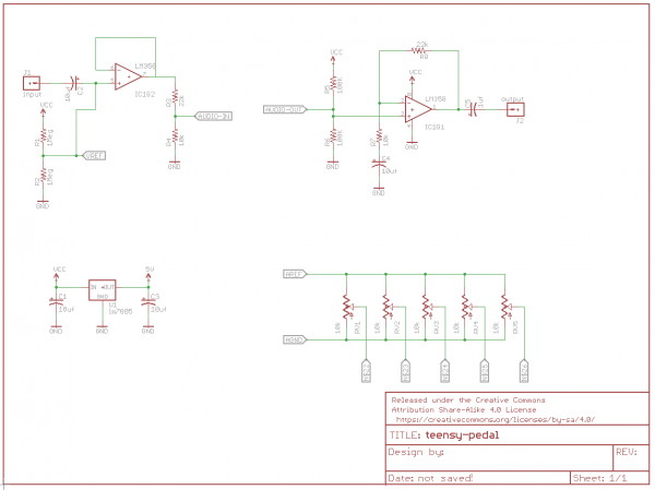
Above is a picture of the circuit in the pedal found at https://learn.sparkfun.com/tutorials/proto-pedal-example-programmable-digital-pedal.
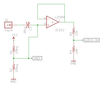
All of my understanding of the circuit comes from the tutorial and Jim. The first piece of the circuit is the input. The input signal is coupled to two 1M Ω resistors by a 10 uf capacitor. The capacitor here serves as a short for the audio current but can be effectively removed for the DC current, allowing the biasing resistors to do their job. The resistors here bias the signal to 4.5 VDC. This is to keep the current between 0V and 9V to be fed into the LM358 operational amplifier that is connected. The op-amp is incredibly important to the circuit. It increases the input impedance, but the output is the same as the input signal. This is important for the guitar. The high impedance allows the guitar’s signal to be passed through cleanly without messing with the tone or volume of the signal.
The output of the op-amp is then attenuated by roughly 1/3 in order for the signal to pass through the Teensy. Because this circuit is powered directly by the 9 VDC power supply, the circuit ends up with about 3 V, the input headroom of the Teensy.
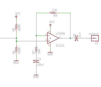
This section is the output of the circuit. The operational amplifier here has a gain of 3 to amplify the output back to 9V as the output of the Teensy is 3 V. This is due to the resistor in the feedback loop. As the signal is passed through, it gets multiplied by the inverse of the ratio early, or about 3. Just like in the input, there are two biasing resistors here. Again, the DC voltage becomes 4.5. This becomes a problem, though, if it were to pass straight through the op-amp with a gain of 3. The voltage would be multiplied to 13.5, so to solve this problem, the fourth capacitor is put in place. Just like the first capacitor, this allows the op-amp to act as a follower for the DC current, so 4.5 VDC is passed through to the output while the audio signal is multiplied.
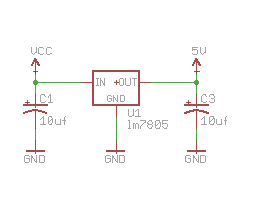
The final piece is the voltage regulator. Because the 9V battery (or wall input) is too high for the Teensy and circuit, this regulator bumps the voltage down to 5V.
This is what I’ve built so far:

Tools and Materials
Currently, I’m just soldering all of the materials that I bought from Sparkfun. Here is the material list:
- 5 electrolytic decoupling capacitors (15uf/25V)
- Teensy 3.2
- Teensy audio board
- DIP sockets solder tail
- LM 358 operational amplifier
- Stranded and solid-core wire
- Break away headers
- Resistors
- 5V voltage regulator
- 5 black knobs
- 5 rotary potentiometers
- Solder
- Soldering iron
- Cutters
- Wire Strippers
- Sparkfun proto pedal
- Chassis
April 24th, 2018 at 2:48 pm
It seems like this is what you’re working on right now but do you have a sense of what the function of the circuit versus the software is? Is the circuit there just to take the input and feed it to the Teensy and then feed the output to the amp or does it also take part in the manipulation of the signal?
April 24th, 2018 at 5:37 pm
The circuit is basically just to flow through the Teensy. All the effects come from the Teensy!
May 2nd, 2018 at 1:52 pm
How much flexibility does the Teensy coding part give you in terms of the effect? Or is that handled in hardware?
May 2nd, 2018 at 5:05 pm
From what I understand, pretty much any effect can be made, but I could be wrong.