Final Update (5/10)

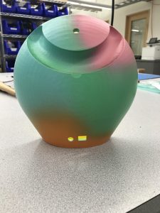
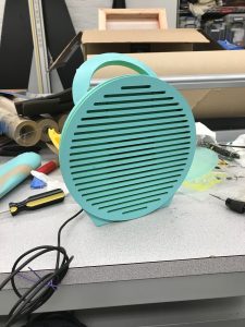
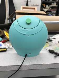
We successfully completed our speaker!


After a full day in the lab, our speaker is fully constructed:

In the final stages of construction we faced many unexpected problems, and had many small tasks that needed to be worked on.

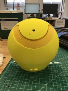
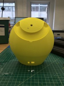
Once Jim explained the completed circuit to us, we got down to the mechanical components and manufacturing. We coated the 3D printed materials and sanded them down until smooth, and then coated them in our chosen shades of paint. We then attached the handle through internal holes and steel rods that we cut to size. This was our first lesson in design and construction: the rods had no way of staying put, and so more foresight into this part of the design was needed.

Once the handle was in, we placed the circuit in place and pulled the top knob through the hole and secured it with a nut. The buttons we printed fit right on top. Next, we filled the extra space of the body with foam.

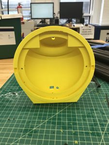
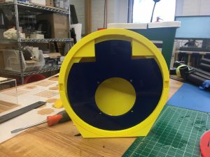
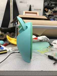
The next step was to place in the internal panel (the driver mount) with the driver and screw it all into place. Here is where we faced our most difficult challenge. We realized that the way the pieces were designed meant that two parts needed to be screwed securely from behind in order to hold in place, but as we would screw one, the other would be blocked, and vice versa. After struggling with this for a long time, we decided that we would glue nuts onto the back of one of the pieces. Then we would screw in the other, and finally, screw the original one only from the front, but because the nuts were already in place, the structure would stay intact.

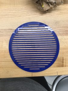
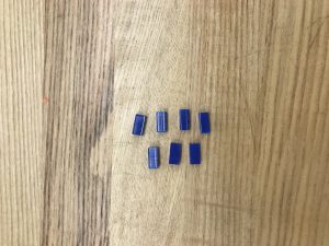
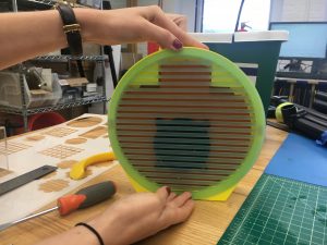
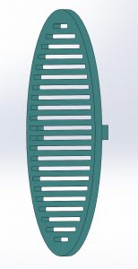
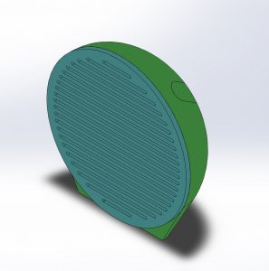
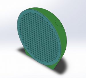
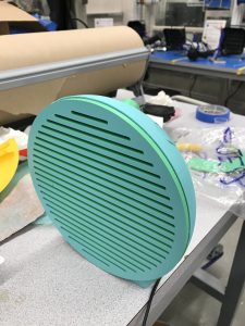
With all of that assembled, we attached the 3D printed rectangles to the sides of the faceplate and force-fit the plate onto the body of the speaker. Finally, our speaker was complete!

And then we were able to plug in, turn it on, and turn up the volume:

speaker-vid

At that point, we could finally try to analyze the sound. After speaking with Jim and Professor Wood, we discovered that much of speaker analysis is subjective. We were advised to play through the speaker and simply talk about what we heard. We decided to play a chirp, as well as a tone at varying frequencies. At first, as we increased the volume, the sound became much more buzzier. We realized that to fix this, we could increase the foam insulation within the speaker, and so we did. The sound became much clearer. We were curious to see what frequencies were audible through our speaker; another specification that could determine the success of our speaker. We played a chirp from about 20 Hz-1000 Hz. It only became audible about halfway through the chirp, or at about a few hundred Hz. This seemed to be pretty good, but of course, a nicer speaker that could push more air through it would be able to be heard at even lower frequencies. Lastly, we noticed that as we varied the frequency of the tone played, that it sounded much quieter as it got lower, even though we did not touch the volume knob. In the end, we realized that this is due to our ears and how we hear sound, and not the configuration of our speaker. In the end, our speaker still did have a slight buzzing sound due to the grill in the front. The long, slender beams of the grill vibrate with the sound waves from the driver and react with the body to create a buzzing sound.


Reflection: This was such an exciting process and we are so excited to now have these amazing looking, fully functioning speakers! If we had had more time, we would have loved to spend more time on the quality of sound analysis. Many things came up last minute in terms of construction, and so we only just recently finished the build part of our project, and therefore the analysis was left to be mostly up to our ears as Jim suggested is usually more effective anyway. Although he believes this is more than sufficient, it would have been cool to be able to record the speaker with a very nice microphone and really see what we are hearing. Throughout our project we relearned so many things from our course from how we hear tones to how sound it transmitted, and of course how a speaker functions, from first input to final output. We got to really see this process through and gain a strong understanding of what goes into projecting sound. We also gained many skills that we were particularly interested in- in designing and designing for manufacturing. We definitely learned a lot of lessons in this area (most of which are included throughout this blog) and have taken a lot from this project.


Big thank you to Jim!!!!!!!!!!!!!!!!

Update 4: 5/9

We are almost done with the manufacturing part of our project. We will then add one more update on the Analysis of Sound once the entire product is constructed.

We printed the first model of our Casing and Handle (each in yellow below). When testing the fit, they were perfectly compatible when is rest position, but as we tried lifting the handle, the shape of the cut out in the body of the casing interfered. This was our first challenge. We then redesigned the fit of the two pieces to allow for a smoother movement when using the handle.


We also laser cut afew pieces to begin testing forsize. We cut a front face plate with slotted lines (blue below) to cover the entire electrical circuit. We also cut an internal panel to hold the driver. The last piece was small rectangle to attach the face plate to the casing body with a force fit. We had some problems here as well. The hole in in the internal panel for the driver was too largeand would not align correctly, so we redesigned it until it fit. The force fit pieces were too small and would not hold the face plate in place and so we enlarged them as well until they were the correct size. All of these small design decisions would add up to allowing us to build a fully functioning speaker.


We also began testing colors in order to see what we liked on the 3D printed materials. If you have any opinions on the choices below, let us know!


Lastly, with all of our minor adjustments, we had to adjust the layout of our circuit and Jim has been incredible with helping us fit the circuitry into any design we have created! By tomorrow we should have it all put together and will update on our success!

Update 3 (4/25)

Our next update has 2 main components addressing the two constructed parts of our speaker: The mechanical elements, and the electrical elements.


Mechanical Update:

As we continued to discuss our ideas for the housing of the speaker, we discovered that the thermoforming materials that we have access to are only applicable to fairly thin plastics. This would make it a more flimsy product than our original intended vision. In order to provide more structural support for the casing, we now plan to 3D print the back, rounded casing. We hope to begin manufacturing in the next few days. Updated CAD model images are included below.

Casing:


Figure 1 and 2: Layered protrusions from the body which support the handle axels and driver mount.

Figure 3: back of speaker with recessed handle, user handle indentation, hole for volume control potentiometer, and audio jack and micro usb ports.


Fixtures:                                                                     

Figure 4: Driver mount with screw holes for driver and connection to casing.

                  Figure 5: Driver mount with screw holes for driver and connection to casing.

Figure 6: Profile section view of faceplate and driver mount in casing. Casing and driver mount form an airtight seal.


Complete Assembly:

Figure 7: Complete Speaker Assembly


Electrical Update:

Below we have included the schematics for the electrical circuit to drive our speaker (thank you Jim!!). The general idea of the circuit is that there is a Li-Poly battery that gives us the Voltage needed to run the speaker. We then regulate the 5V down to about 4.2V. There are then 2 mirroring circuits that will affect volume control and amplify the sounds slightly. From there, we sum these two signals, and finally input them into a (NAME) chip which acts very similarly to a PWM (control?) which will “magically do the work for you!” -Jim. This output is then connected directly to our driver to produce the intended level of sound.

More specifically, here is a description of the circuit (as described by Jim):

This amp is designed to power a small speaker in a small enclosure, from a variety of sources, including headphone jacks and line outputs.  It features a rechargeable battery which is charged through a standard micro-USB connector.
The charger circuit is U2, in the lower left of the schematic.This chip is designed to take a 5V input from a USB cable and charge a lithium-ion battery to its maximum voltage of 4.2V.  The battery is connected to J2, to the right of U2.  The resulting power source can vary from 4.2V down to 3.5V or lower when the battery discharges.  That’s not a lot of voltage, so the rest of the components need to be specially chosen to run on lower voltage.  In particular, I needed to find a low-voltage operation amplifier, so I chose the LME49721
One of the problems with running off of batteries is that audio signals are both positive and negative with respect to ground, so you will see a lot of capacitors in the signal path, whose job is to allow me to shift the signals so they’re centered around a point halfway between Vcc, which is the battery’s voltage, and ground.  That’s the job of voltage divider R24-R25 on the left.

Stereo audio comes in on J3 in the upper left and gets attenuated by ganged potentiometers R10 and R18.  Putting the signals through potentiometers before going into op-amps is a way to allow the amp to work with large signals that would otherwise have caused the amps to clip.

The main job of U3A and U3B is to present a high input impedance to whatever is driving the amp, but they also add a bit of gain — a factor of two in the audio band.  We can adjust this gain by changing resistor values if needed, after listening to the speaker through your phones.

Once through U3, the left and right channels are summed together by inverting summer U4.  The output of U4 then goes to the magic digital speaker driver U6.
The SSM2305’s operation is similar to the PWM amplifier that Landon from Bose talked about, but it’s a bit more complicated than the PWM concept — it uses a technique called Sigma-Delta modulation.

Update 2 (4/20)

Design Approach:

Below is an image of our CAD model for our speaker. It is 8.5in x 8.5in and 3.2 inches deep. The thought process behind these dimensions was that we wanted it to be portable, while not miniature. We are bringing the boom box back. This also allows enough depth for most drivers that we will decide between to fit within the housing.


The materials we have chosen for our housing are mainly acrylic (for the front piece) and plastic to be thermoformed into the back casing. The reason we chose to thermoform is because it allows us to create the entire back half from a single piece of plastic using a simple mold to create our exact intended shape, and it is a lot faster than 3D printing the piece. The acrylic front allows us to shape it easily with laser cutting, and cut slots throughout the front. While the decisions we have made for these materials are mainly focused on manufacturing considerations, we are not worried about their affect on the sound. We plan to fill the inside of the casing with a foam material to reduce the sound waves reflected off of the casing itself.

Below is also an image of our intended circuit within the housing unit. This may change as we determine the driver we plan to use, but we will update this page as our design changes. We also have a list of the components and connections shown.

(Source: https://makezine.com/projects/make-34/monobox-powered-speaker-2/)

Update 1 (4/13)

Introduction:
Welcome to our ES25 Final Project Site! We are excited to learn about designing and building a speaker and hope you enjoy the process of our work. We specifically aim to explore speaker casing design with the ultimate goal of finding out how far we can creatively push current speakers from an industrial design point of view. Here we will include weekly updates on our progress, design decisions, and problems that we face along the way.

Project Description:
We plan to build a working speaker, housed in a mechanical structure we design and fabricate ourselves. We will soon include a CAD mockup of what this will look like, which will shape the electrical components we choose to buy. Our speaker is inspired by the boomboxes of the late 1990s and takes geometric inspiration from appliances from the 1950’s. Based on our current vision, our speaker will consist of an acrylic front plate slotted with holes through which the sound is emitted. The back of the housing will be a rounded, thermal formed plastic casing. Within this casing, we will solder circuitry to connect speaker driver to a jack to plug in a phone. Once we get this to work, we will be able to analyze how this given geometry affects the sound from the speaker, and learn about geometries that will optimize the sound.

Motivation:
We chose to explore this specific aspect of speakers because we are both mechanical engineering students interested in product design. In a class combining music and engineering, we knew that we wanted to build something physical, and a speaker seemed like an exciting challenge. While we could have attempted to experiment with the electrical components of the speaker, many of the tutorials and how-tos we found online recommended strongly against doing so since the technology surrounding the electrical components is so complex and would require intense studying. More importantly, this project will allow us to gain real design experience as well as manufacturing skills to bring our design to life. These challenges and opportunities are what drove us to choose this project.

Background Research (how have similar problems been solved by others?):
  • Most housings are made of wood (easy to work with or materialistically preferable?)
  • Many subcategories of designs: single subwoofer designs, dual subwoofer designs
  • For-sale design specifications
  • Complicated speaker box online calculators (ex.) that take into account factors like width, height, depth, driver displacement, port displacement, wood thickness, etc.
  • First decide frequency range hoping to achieve – (particularly the low frequency extension) will guide some basic dimensions related to the speaker cabinet design.
  • Most basic and easy to understand shape is a cube/rectangular prism. Need more sophisticated software to truly understand more complex shapes.
  • Well designed speakers need to be designed with a speaker software.
  • Basic Designs:
    • Sealed enclosure: A box, of whatever shape you wish, that is air tight -easiest enclosure to design and build. Stuffing the box with sound dampening material absorbs stationary waves produced by the back of the speaker and yields better results.
    • Infinite baffle: baffle extends in all directions so even the longest sound waves don’t reach the edge of the baffle. The waves created by the back of the speaker never meet the waves created by the front of the speaker = no resonances, no diffraction. Cannot be perfectly implemented in real life. Real world= sealed box large enough so the air inside the box will not alter the compliance of the driver.
    • Bass reflex/ported/vented: great balance between sound quality, output/efficiency, design and build difficulty. Port with predefined length and diameter to set the resonant frequency. Resonant frequencies come out the back of the speaker, reverse their phase and come out the port, adding with the waves from the front of the speaker. Alternative: passive radiator.
    • Bandpass (of various orders): 4th order bandpass – one side of the speaker is placed in a sealed enclosure, while the other side is placed in a ported enclosure. The woofer plays louder than bass-reflex, but has a narrow frequency response.
    • Transmission Line: Labyrinth on the back side of the speaker. Back waves generated by the speaker, travel through this labyrinth, which has a fixed length directly correlated to the wavelength of the resonance frequency of the speaker in free air. When the waves come out, they are in phase with the waves generated by the front of the speaker. Challenge: filling with specific pattern of damping material of different thicknesses and densities so all of the upper frequencies are absorbed.