Final Update
May 9th, 2018
Update #4
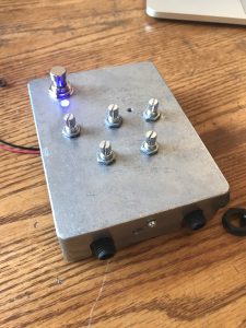
Output
Description
I finished the build portion of my pedal on Tuesday, and the tutorial came with some pre-made code to run on the board. After discussing my options with Ben, we decided that the software from the tutorial would be best to use. The code I am using in the pedal creates an Auto Roller effect. This simulates a rotary tone cabinet which creates a “dynamically-controlled warble.” The louder the guitar is played, the faster the oscillation of the wave. The code I used can be found here: https://github.com/sparkfun/Proto_Pedal/blob/master/projects/teensy-based/sketches/AutoRoller/AutoRoller.ino


How it works
The pedal is built with five knobs, and the Auto Roller has five different controls: tone, speed, depth, high EQ, and low EQ.
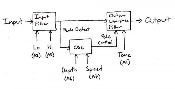
Image from https://learn.sparkfun.com/tutorials/proto-pedal-example-programmable-digital-pedal
The first stage of the effect is the input filter. Within this filter are two different parameters, low frequency control and high frequency control. These are very simple low- and high- pass filters. When the low frequency control is turned fully clockwise, all the low frequencies are passed through. When it’s turned fully counterclockwise, the low frequencies are cut out. The same happens with the high frequency control except with high frequencies.
This signal feeds into a peak detector module. The harder the guitar is hit, the faster and deeper the effect. This module changes the frequency and amplitude of the sine wave generated by the algorithm based on the input from the guitar, and this is the most interesting section of the effect. In addition to the dynamic control of the sine wave’s oscillation, the algorithm also includes a frequency oscillator that can be controlled by the knobs. The depth knob changes the amplitude of the sine wave. Fully clockwise, the effect is in full force and extremely noticeable. Counterclockwise, it’s basically off. The speed knob changes the frequency of the sine wave. Clockwise, the warbling effect is faster. Counterclockwise, it isn’t noticeable.
Finally the signal is passed through another low-pass filter that control the overall tone of the effect. The tone knob changes the cut-off frequencies when engaged. Like any low-pass filter, when the tone knob is turned counterclockwise, all the high frequencies are cut and creates an interesting sound like a whale under water. When turned fully clockwise, the tone knob doesn’t attenuate any frequencies. Additionally, this knob also changes the resonance of the effect. When it is fully clockwise, the knob has very little resonance, so the effect is barely noticeable. The opposite occurs when the knob is counterclockwise, and the effect is very noticeable.
Performance
The pedal works really well. The auto-roller that sounds amazing, and it is really versatile. I’m glad that the electronics work and the Teensy is able to download the code I want to run. Some little things are slightly off with the sound, though. Unfortunately, the noise floor of the Teensy is raised, so when the pedal is plugged in, there is a slight buzzing sound. This is due to the Teensy itself. It also could be due to the fact that I used non-audio specific capacitors which Jim said might have an effect on the output. However, when I play guitar, it isn’t noticeable. I don’t have much to base the performance of the pedal off other than my own store-bought pedals, but compared to those, my pedal actually sounds like a professionally made pedal. The effects sound as good as any pedal I’ve used, and I’m excited to add this to my board.
Reflection
Through this process, I learned a lot about circuitry, electrical engineering, and effects. Before this class, I had no knowledge of engineering in any regard, and this project helped me understand the things we learned in class on a deeper level. I certainly applied the concepts of circuitry that we learned throughout the class. I didn’t really have a grasp on the concepts while we were in class, but this process helped me develop a deeper understanding. Additionally, I applied many of the concepts we learned with regards to effects, filters, oscillators, and coding. These are things I had a better grasp on, but I still gained a lot from this experience.
Additional pictures


Third Update
April 25th, 2018
Update #3
Build
Build Overview
Building this pedal has proved challenging but fun. So far, I’ve built much of the hardware based on the tutorial online. The one change I made was in the microfarads of the capacitors. The lab did not have the 10 microfarads capacitors I needed, so Evan from the Active Learning Labs told me that, since they are just being used for decoupling, that I can use 15 microfarad capacitors instead. The incremental tests throughout the build have worked, so it seems like the change will not effect the build. I plan on finishing by next Wednesday to give myself time to mess with the software components and address any issues I might have with the hardware.
Challenges
One of the biggest challenges I’ve had so far has been with soldering. Our first lab was the first time I had ever soldered, so I’m not particularly good at it. However, for the most part, I’ve done a fine job of making sure everything is in its right place. That being said, during my first session building the hardware, I made a mistake and placed a capacitor in the wrong space. I rushed the process, and soldered the capacitor without checking that I had placed it correctly. It took me about 20 minutes to figure out how to remove the capacitor and replace it, but afterwards, I did an incremental test on the voltage being produced by the circuit, and I was within the range the tutorial suggested. As it appears now, my mistake did not hurt the circuit, and I learned a valuable lesson to not rush myself while building.
Additionally, it has been difficult to actually place the pieces in the right space. This is less of a challenge and more of an annoyance, but I have large fingers, so making sure centimeter long wires are fitting in the small circuit board has been difficult. Overall, though, I’ve enjoyed building the pedal.
A new challenge that I’ve come across involved building the chassis. Sparkfun had their pre-made chassis on backorder, so I decided to buy a metal box with no holes drilled. I am not adept at drilling, so Maddie helped plan where the holes should be drilled and taught me how to do it. However, the holes I made were slightly off, so I wasn’t able to fit the circuit board into the chassis. It took me a few tries, but eventually I just sanded the hole through the box, and it fit. However, the whole I drilled for the power supply was off-center, so I have to use a battery. That’s not a problem, though, because batteries sound better than wall plugs!

Second Update
April 20th, 2018
Update #2
Design
Schematics
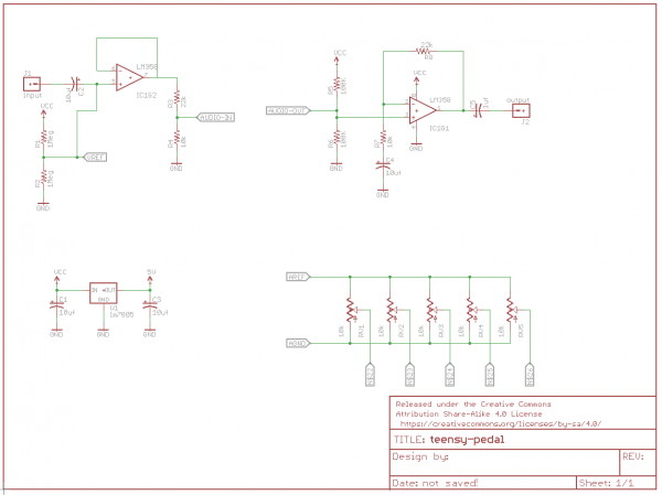
Above is a picture of the circuit in the pedal found at https://learn.sparkfun.com/tutorials/proto-pedal-example-programmable-digital-pedal.
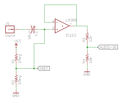
All of my understanding of the circuit comes from the tutorial and Jim. The first piece of the circuit is the input. The input signal is coupled to two 1M Ω resistors by a 10 uf capacitor. The capacitor here serves as a short for the audio current but can be effectively removed for the DC current, allowing the biasing resistors to do their job. The resistors here bias the signal to 4.5 VDC. This is to keep the current between 0V and 9V to be fed into the LM358 operational amplifier that is connected. The op-amp is incredibly important to the circuit. It increases the input impedance, but the output is the same as the input signal. This is important for the guitar. The high impedance allows the guitar’s signal to be passed through cleanly without messing with the tone or volume of the signal.
The output of the op-amp is then attenuated by roughly 1/3 in order for the signal to pass through the Teensy. Because this circuit is powered directly by the 9 VDC power supply, the circuit ends up with about 3 V, the input headroom of the Teensy.
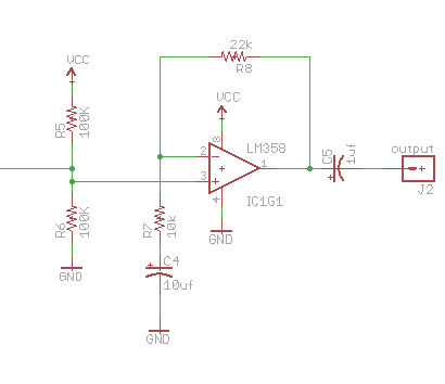
This section is the output of the circuit. The operational amplifier here has a gain of 3 to amplify the output back to 9V as the output of the Teensy is 3 V. This is due to the resistor in the feedback loop. As the signal is passed through, it gets multiplied by the inverse of the ratio early, or about 3. Just like in the input, there are two biasing resistors here. Again, the DC voltage becomes 4.5. This becomes a problem, though, if it were to pass straight through the op-amp with a gain of 3. The voltage would be multiplied to 13.5, so to solve this problem, the fourth capacitor is put in place. Just like the first capacitor, this allows the op-amp to act as a follower for the DC current, so 4.5 VDC is passed through to the output while the audio signal is multiplied.
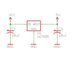
The final piece is the voltage regulator. Because the 9V battery (or wall input) is too high for the Teensy and circuit, this regulator bumps the voltage down to 5V.
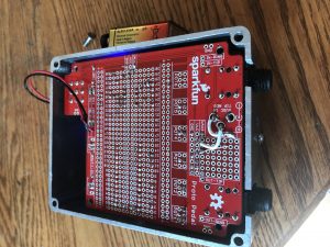
This is what I’ve built so far:

Tools and Materials
Currently, I’m just soldering all of the materials that I bought from Sparkfun. Here is the material list:
- 5 electrolytic decoupling capacitors (15uf/25V)
- Teensy 3.2
- Teensy audio board
- DIP sockets solder tail
- LM 358 operational amplifier
- Stranded and solid-core wire
- Break away headers
- Resistors
- 5V voltage regulator
- 5 black knobs
- 5 rotary potentiometers
- Solder
- Soldering iron
- Cutters
- Wire Strippers
- Sparkfun proto pedal
- Chassis
First Update (4/13)
April 10th, 2018
Friday Update #1
Project and Motivation
For my final project, I’m going to be building a reprogrammable guitar effects pedal. I will be closely following a Sparkfun tutorial to build the hardware. The pedal will use a teensy to control the effects, so that is where the project will get creative. There are a number of pre-made effects already online, but I want to build my own custom phaser or flanger. This will be the more time-intensive part of the process, but perhaps the more fulfilling.
This project’s motivation comes from a love of guitar and guitar effects. My own pedal board already has a number of effects (chorus, overdrive, delay), but to complete my sound, I want to add some new effects. Because the pedal is reprogrammable, if I want a different effect for a different recording, I can take the time to make the new effect (albeit not on stage, that would be kind of time-consuming). I really enjoyed playing with Max for our last lab, so I’m excited to mess around with the effects and sounds that it can produce.
Background Research
Building a guitar pedal is pretty difficult to do from scratch. It involves complex circuitry and design, and a in-depth knowledge of sound and effects. Luckily, there is a tutorial online for building the pedal I want to build: https://learn.sparkfun.com/tutorials/proto-pedal-example-programmable-digital-pedal. Like I said, I will follow this tutorial to build the hardware.
Along with the tutorial are a number of pre-made effects: https://github.com/sparkfun/Proto_Pedal/tree/master/projects/teensy-based/sketches. Using these as a starting point, I will build and change them as best I can to create the effects I want.